
Thursday, June 17, 2010


Wednesday, June 16, 2010


Monday, May 31, 2010
Skill Module- Group Problem Solving

Principles » Don’t jump to solutions before defining the problem » Solve problems close to the source » Attend to the interests of all stakeholders » Team-based knowledge driving systems change
Skills » Brainstorming » Facilitation and mediation » Process improvement
Skills » Brainstorming » Facilitation and mediation » Process improvement
Thursday, May 20, 2010
Tower Crane Research


Tower cranes are a common fixture at any major construction site. They're pretty hard to miss -- they often rise hundreds of feet into the air, and can reach out just as far. The construction crew uses the tower crane to lift steel, concrete, large tools like acetylene torches and generators, and a wide variety of other building materials.
Parts of a Tower CraneAll tower cranes consist of the same basic parts:
The base is bolted to a large concrete pad that supports the crane.
The base connects to the mast (or tower), which gives the tower crane its height.
Attached to the top of the mast is the slewing unit -- the gear and motor -- that allows the crane to rotate:
The base is bolted to a large concrete pad that supports the crane.
The base connects to the mast (or tower), which gives the tower crane its height.
Attached to the top of the mast is the slewing unit -- the gear and motor -- that allows the crane to rotate:
On top of the slewing unit are three parts:
The long horizontal jib (or working arm), which is the portion of the crane that carries the load. A trolley runs along the jib to move the load in and out from the crane's center:
The long horizontal jib (or working arm), which is the portion of the crane that carries the load. A trolley runs along the jib to move the load in and out from the crane's center:
The shorter horizontal machinery arm, which contains the crane's motors and electronics as well as the large concrete counter weights:
The operator's cab:
The machinery arm contains the motor that lifts the load, along with the control electronics that drive it and the cable drum, as shown here:
The motors that drive the slewing unit are located above the unit's large gear:
Why Don't They Fall Over?When you look at a tall tower crane, the whole thing seems outrageous -- why don't these structures fall over, especially since they have no support wires of any kind?
The first element of the tower crane's stability is a large concrete pad that the construction company pours several weeks before the crane arrives. This pad typically measures 30 feet by 30 feet by 4 feet (10 x 10 x 1.3 meters) and weighs 400,000 pounds (182,000 kg) -- these are the pad measurements for the crane shown here. Large anchor bolts embedded deep into this pad support the base of the crane:
The first element of the tower crane's stability is a large concrete pad that the construction company pours several weeks before the crane arrives. This pad typically measures 30 feet by 30 feet by 4 feet (10 x 10 x 1.3 meters) and weighs 400,000 pounds (182,000 kg) -- these are the pad measurements for the crane shown here. Large anchor bolts embedded deep into this pad support the base of the crane:
So these cranes are essentially bolted to the ground to ensure their stability. In the next section, you'll learn how tower cranes "grow."
SLIDESHOW:
safety features. past and present accidents
how much weight can a tower crane lift
The Engineering Design Process
Elements of Design the Process
-Problem Identification
-Research Phrase
-Requirements Specification
-Concept Generation
-Deisgn Phase
-Prototyping Phase
-System Integration
-Maintenance Phase
Needs Identification
What is the Problem?
1.Collect information
2.Interpret information
3.Organize needs hierarchy
4.Determine relative importance of needs
5.Review outcomes and process
Concept Generation and Evaluation
Explore many solutions
-Brainstorm
Select the best solution
-Based on needs and constraints
Creativity
-Development of new ideas
Innovation
-Bringing creative ideas to reality
Concept Generation
-Substitute
-Combine
-Adapt
-Modify
-Put to other use
-Eliminate
-Rearrange or reverse
Barriers to Creativity
Perceptual blocks
• Limiting problem space
Emotional blocks
•Fear of failure – “fail early and often”
Environmental blocks
• Engineering cultural bias
Intellectual and expressive blocks
• Understand tools
Design Group (Team)
Hold effective meetings
1.Have an agenda
2.Show up prepared
3.Pay attention
4.Schedule time and place of next meeting
5.Summarize
Assign tasks and responsibilities
Engineering projects require diverse skills
This creates a need for group (team) work
Select members based on skills
1.Technical
2.Problem-solving
3.Interpersonal
Develop decision making guidelines
1.Decision by authority (leader)
2.Expert Member
3.Average member opinion
4.Majority
5.Consensus
Project Management
Work breakdown structure
Hierarchical breakdown of tasks and deliverables need to complete project
Activity
1.Task – action to accomplish job
2.Deliverable – e.g. circuit or report
Friday, May 14, 2010

Thursday, April 29, 2010


Friday, April 23, 2010


Thursday, April 22, 2010

Monday, April 19, 2010
Journals
Week 1
Feb. 2-5th 2010
February 2, 2010In todays class we learned about; Introduction to technical drawings.Moodle: Post number 4;Basic Drawing Equipment 1-3, (highlights)BASIC DRAWING / OFFICE EQUIPMENT - 1--drawing Pencils- a range from 2Bto 2H--A refillable pencil-is very useful especially if you are constructing a drawing that needs a constant thickness of line. (disadvantages: the refillable pencils are relatively expensive and so are the refills. Also, the leads tend to break more easily.)--Compass--Ink fountain pens--A protractorBASIC DRAWING / OFFICE EQUIPMENT - 2--A fine pen (colour - normally black)--T-Squares -are use to draw horizontal lines.--Set Squares-are used to draw accurate angles.--Board clips-are used to hold the drawing paper in position.--A ruler-is possibly one of the most important pieces of drawing equipment.BASIC DRAWING / OFFICE EQUIPMENT - 3--Circle templates--A craft knife-is used to cut out card shapes--scissors--Pencil sharpeners--A craft knife
----------------------------------------------------------------------
EXPLODED VIEW-part of techincal drawing.Exploded views are often a good way of showing detail. The drawings below show two types of similar pens. One is a fine line felt pen used for drawing precise, fine lines. The other is a fountain pen and it is used to write letters etc.... Both pens have been drawn as ‘exploded views/drawings’. In an exploded drawing the pens are drawn with all their parts disassembled (taken apart). It is important to recognise that all the parts are in line with each other, drawn usually along a centre line which is drawn through the centre of the design.
----------------------------------------------------------------------
ORTHOGRAPHIC PROJECTION or MULTIVIEW DRAWINGS
1. Introduction to Third Angle Orthographic Drawing2. Third Angle Orthographic Drawing - an Example3. Third Angle Orthographic Projection - Further Explanation4. Wind Power Device - Orthographic Drawing5. First Angle Orthographic Projection6. Dimensions (Measurements)7. Working Drawings8. Orthographic Drawing - Mobile Phone Example9. Stages of Drawing a Mobile Phone in Orthographic10. Presentation of an Orthographic Drawing11. Orthographic Drawing Exercise
Week 2
Monday February 8th 2010
today in class we watched a video from youtube called 'Machine Shop Tools for Measurement'. Following with a question sheet called,' Mr.Martin's Metric to Imperial Assignment".
Applying the Metric and Imperial Systems of MeasurementSystems of measurement are used to measure the length, volume, mass or temperature of an object.this is posted on my blog already, the entire Metric and Imperial Systems of Measurement work page.
Tuesday, February 9th, 2010
We started working on the Mechanical Drawing test: reading dimensions workpage on CAD. We used the isometric drawing by reading the dimensions on the drawing on the page and created it on CAD. I did not finish this today.
Wednesday, February 10th, 2010
I finished the Mechanical Drawing Test on CADNow i had to save on model paper and load it to the blog.
Thursday, February 11th 2010
Went onto google sketch and created a dog house, while watching a video on youtube on how to create a dog house with google sketch.
Week 3
Tuesday February 16th 2010
Artistic Drawing / Perspectiveworked on the car on google sketch
Wednesday February 17th 2010
WHMIS testworked on the car on google sketchWe then started to ratate the pieces of the car so that they could create a 3d looking vehicle
Thursday February 18th 2010
Posted the car onto the blog. unfinished but mr. D said we would finish it some other time.Started to create our roller coaster on google sketch
Week 4
Monday February 22nd 2010
Worked on Google Sketch on our roller coasters. We continued making the support beams
Tuesday February 23rd 2010
We did quiz's http://highered.mcgraw-hill.com/worked on google sketch on roller coaster and continused making the support beams
Wednesday, February 24th 2010
Worked on Roller Coaster
Week 5
Monday March 1st
Today I worked on my roller coaster, i was making a huge hill.. and had to work on making it smoother then it was on the edges.
Tuesday March 2nd
I continued working on my roller coaster
Wednesday March 3rd
I continues working on my roller coaster. I worked on turing my roller coaster , which took me awhile to figure out how to.
Thursday March 4th
I continued working on my roller coaster adding three loops into my roller coaster
Friday March 5th
I continued working on my roller coaster and started making my support
Week 6
Monday
Continued to work on the roller coaster assignment and started to work on animating it. Tomorrow will be a continuation of the animation
Tuesday
Continued to work on roller coaster animation
Wednesday
Continued to work on the roller coaster animation
Thursday
Continued to work on the roller coaster animation
Friday
Continued to work on the roller coaster animation
Week 7
Monday
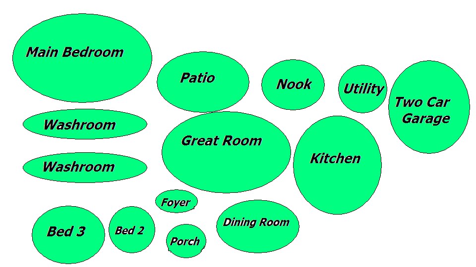
Finished animating my roller coaster started to learn about how to design a residential home on; http://moodle.sjconline.ca/file.php/123/SrHomeDesign.pdf from moodle.
Week 8
Monday, April 9th, 2010
Tuesday, April 10th 2010
Wednesday, April 11th 2010
Thursday, April 12th 2010
Friday, April 13th 2010
Week 9
Monday, April 12th 2010
Tuesday, April 13th 2010
Wednesday, April 14th 2010
Thursday, April 15th 2010
Friday, April 16th 2010
Week 10
Monday, April 19th 2010
Uploaded Elevation Views of house onto blog, Started AutoCAD
Tuesday, April 20th 2010
Wednesday, April 21st 2010
Thursday, April 22nd 2010
Friday, April 23 2010
Week 11
Monday, April 26th 2010
I was not in class on this day, i was away in Toronto
Tuesday, April 27th 2010
I was not in class on this day, i was away in Toronto
Wednesday, April 28th 2010
I was not in class on this day, i was away in Toronto
Thursday, April 29th 2010
I started AutoCAD, i had missed two new CAD drawings, so i had to catch up today
Week 12
Monday, May 3rd 2010
Tuesday, May 4th 2010
Wednesday, May 5th 2010
Thursday, May 6th 2010
Friday, May 7th 2010
We started to do a workbook that we had to finish over the weekend, we did not use the computer and worked on this workbook the entire period.
Week 13
Monday, May 10th 2010
started and finished orthographic missing view exercise sheets
Tuesday, May 11th 2010
Orthographic and isometric drawings worksheet. I handed this in and then worked on the next assignment in autoCad.
Wednesday, May 12th 2010
Today i continued to work on my control braket in Auto Cad. I began to draw each side and learned a few new tools such as the quad tool and the fillet tool. Each of these tools i had to use when rounding my corners and drawing the proper hidden lines.
Thursday. May 13th 2010
Today I continued to work on my controld bracket in AutoCad once again.
Week 17
Monday, June 7th 2010
Feb. 2-5th 2010
February 2, 2010In todays class we learned about; Introduction to technical drawings.Moodle: Post number 4;Basic Drawing Equipment 1-3, (highlights)BASIC DRAWING / OFFICE EQUIPMENT - 1--drawing Pencils- a range from 2Bto 2H--A refillable pencil-is very useful especially if you are constructing a drawing that needs a constant thickness of line. (disadvantages: the refillable pencils are relatively expensive and so are the refills. Also, the leads tend to break more easily.)--Compass--Ink fountain pens--A protractorBASIC DRAWING / OFFICE EQUIPMENT - 2--A fine pen (colour - normally black)--T-Squares -are use to draw horizontal lines.--Set Squares-are used to draw accurate angles.--Board clips-are used to hold the drawing paper in position.--A ruler-is possibly one of the most important pieces of drawing equipment.BASIC DRAWING / OFFICE EQUIPMENT - 3--Circle templates--A craft knife-is used to cut out card shapes--scissors--Pencil sharpeners--A craft knife
----------------------------------------------------------------------
EXPLODED VIEW-part of techincal drawing.Exploded views are often a good way of showing detail. The drawings below show two types of similar pens. One is a fine line felt pen used for drawing precise, fine lines. The other is a fountain pen and it is used to write letters etc.... Both pens have been drawn as ‘exploded views/drawings’. In an exploded drawing the pens are drawn with all their parts disassembled (taken apart). It is important to recognise that all the parts are in line with each other, drawn usually along a centre line which is drawn through the centre of the design.
----------------------------------------------------------------------
ORTHOGRAPHIC PROJECTION or MULTIVIEW DRAWINGS
1. Introduction to Third Angle Orthographic Drawing2. Third Angle Orthographic Drawing - an Example3. Third Angle Orthographic Projection - Further Explanation4. Wind Power Device - Orthographic Drawing5. First Angle Orthographic Projection6. Dimensions (Measurements)7. Working Drawings8. Orthographic Drawing - Mobile Phone Example9. Stages of Drawing a Mobile Phone in Orthographic10. Presentation of an Orthographic Drawing11. Orthographic Drawing Exercise
Week 2
Monday February 8th 2010
today in class we watched a video from youtube called 'Machine Shop Tools for Measurement'. Following with a question sheet called,' Mr.Martin's Metric to Imperial Assignment".
Applying the Metric and Imperial Systems of MeasurementSystems of measurement are used to measure the length, volume, mass or temperature of an object.this is posted on my blog already, the entire Metric and Imperial Systems of Measurement work page.
Tuesday, February 9th, 2010
We started working on the Mechanical Drawing test: reading dimensions workpage on CAD. We used the isometric drawing by reading the dimensions on the drawing on the page and created it on CAD. I did not finish this today.
Wednesday, February 10th, 2010
I finished the Mechanical Drawing Test on CADNow i had to save on model paper and load it to the blog.
Thursday, February 11th 2010
Went onto google sketch and created a dog house, while watching a video on youtube on how to create a dog house with google sketch.
Week 3
Tuesday February 16th 2010
Artistic Drawing / Perspectiveworked on the car on google sketch
Wednesday February 17th 2010
WHMIS testworked on the car on google sketchWe then started to ratate the pieces of the car so that they could create a 3d looking vehicle
Thursday February 18th 2010
Posted the car onto the blog. unfinished but mr. D said we would finish it some other time.Started to create our roller coaster on google sketch
Week 4
Monday February 22nd 2010
Worked on Google Sketch on our roller coasters. We continued making the support beams
Tuesday February 23rd 2010
We did quiz's http://highered.mcgraw-hill.com/worked on google sketch on roller coaster and continused making the support beams
Wednesday, February 24th 2010
Worked on Roller Coaster
Week 5
Monday March 1st
Today I worked on my roller coaster, i was making a huge hill.. and had to work on making it smoother then it was on the edges.
Tuesday March 2nd
I continued working on my roller coaster
Wednesday March 3rd
I continues working on my roller coaster. I worked on turing my roller coaster , which took me awhile to figure out how to.
Thursday March 4th
I continued working on my roller coaster adding three loops into my roller coaster
Friday March 5th
I continued working on my roller coaster and started making my support
Week 6
Monday
Continued to work on the roller coaster assignment and started to work on animating it. Tomorrow will be a continuation of the animation
Tuesday
Continued to work on roller coaster animation
Wednesday
Continued to work on the roller coaster animation
Thursday
Continued to work on the roller coaster animation
Friday
Continued to work on the roller coaster animation
Week 7
Monday
Finished animating my roller coaster started to learn about how to design a residential home on; http://moodle.sjconline.ca/file.php/123/SrHomeDesign.pdf from moodle.
Week 8
Monday, April 9th, 2010
Tuesday, April 10th 2010
Wednesday, April 11th 2010
Thursday, April 12th 2010
Friday, April 13th 2010
Week 9
Monday, April 12th 2010
Tuesday, April 13th 2010
Wednesday, April 14th 2010
Thursday, April 15th 2010
Friday, April 16th 2010
Week 10
Monday, April 19th 2010
Uploaded Elevation Views of house onto blog, Started AutoCAD
Tuesday, April 20th 2010
Wednesday, April 21st 2010
Thursday, April 22nd 2010
Friday, April 23 2010
Week 11
Monday, April 26th 2010
I was not in class on this day, i was away in Toronto
Tuesday, April 27th 2010
I was not in class on this day, i was away in Toronto
Wednesday, April 28th 2010
I was not in class on this day, i was away in Toronto
Thursday, April 29th 2010
I started AutoCAD, i had missed two new CAD drawings, so i had to catch up today
Week 12
Monday, May 3rd 2010
Tuesday, May 4th 2010
Wednesday, May 5th 2010
Thursday, May 6th 2010
Friday, May 7th 2010
We started to do a workbook that we had to finish over the weekend, we did not use the computer and worked on this workbook the entire period.
Week 13
Monday, May 10th 2010
started and finished orthographic missing view exercise sheets
Tuesday, May 11th 2010
Orthographic and isometric drawings worksheet. I handed this in and then worked on the next assignment in autoCad.
Wednesday, May 12th 2010
Today i continued to work on my control braket in Auto Cad. I began to draw each side and learned a few new tools such as the quad tool and the fillet tool. Each of these tools i had to use when rounding my corners and drawing the proper hidden lines.
Thursday. May 13th 2010
Today I continued to work on my controld bracket in AutoCad once again.
Week 17
Monday, June 7th 2010
Tuesday, June 8th 2010
Wednesday, June 9th 2010
Thursday, June 10th 2010
Today i fixed a few things on my blog and we did a note
Friday, June 11th 2010
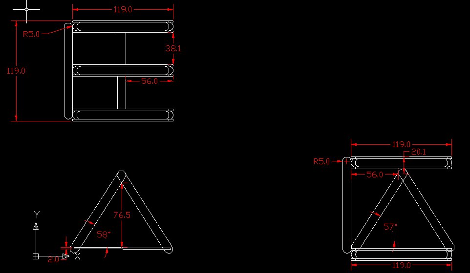
Today we started to design our own crane on auto cad. We had to make our own blue print
Week 18
Monday, June 14 2010
We worked on our tower crane orthographic drawings
Tuesday, June 15 2010
I worked on my orthographic drawing of my tower crane and did research and uploaded a rough draft of my crane to the blog
Wednesday, June 16 2010
Continued to work on my orthographic drawing of my tower crane, and dimensions and such..
Thursday, June 17 2010
Finished my tower crane on AutoCad and started to work on building the crane
Friday, June 18 2010
Continued to work on the tower crane and aswell as finishing our tower crane


Wednesday, April 7, 2010
Engineering Symbols Presentation: Jenn, Brad, Justin
Tolerance
is the total amount a dimension can vary and is the difference between maximum and minimum values. The total allowable variance in dimensions (upper limit-lower limit)Datum-A datum is a theoretically exact point, axis or plane
Tolerance can measure:
-a physical dimension
-a value or physical property of a material, manufactured object, system, or service
-other values such as temperature and humidity
-in engineering and safety, a physical distance or space
-in mechanical engineering the space between a nut and a bolt
Tolerance may be specified as a factor or percentage of a value.
It is a wide ranfe of allowed values that are specified by a note or published standard with information
Tolerance Symbols
-The tolerance value. If the tolerance zone is circular or cylindrical it is represented with a
-Letters for the datums (code) when the tolerance feature is specified in relation to one, or more datums.
Allowance
-A planned deviation between an actual dimension and a nominal or theoretical dimension. Or between an intermediate-stage dimension and an intended final destination.-This means that the engineer would intentionally make the actual dimensions of an object different from the dimensions of the object on paper
Geometric Tolerancing
This is a symbolic language used on engineering drawings and computer generated 3D solid models for explicitly describing nominal geometry and its allowable variation in form and size
The structure of a welding symbol
- The horizontal line--called the reference line--is the anchor to which all the other welding symbols are tied
- Weld instructions are written along the reference line
- An arrow connects the reference line to the joint that is to be welded.
- The flags growing out of the junction of the reference line and the arrow is present if the weld is to be made in the field during erection of the structure
- When two steel plates are joing together in a T shape, welding may be done on either side of the stem of the T
Friday, March 26, 2010

Wednesday, March 24, 2010
Careers in Architecture
Architectural Careers
Beginning Drafter
- - Entry level position to gain experience and skill
Experienced Drafter
- - Expected to make construction decisions based on initial designs
- Positions are available with architects, engineers, and designers
Designer
- - May work under an architect and as a coordinator of many drafters
Architect
- -Must be licensed to practice
- -Designs residential and commercial buildings
- -Additional schooling beyond high shcool required
- -A variety pf architectural careers available
Engineer
- Work is more technical and requires high level of math and science
- Education beyond high school required
- A variety of engineering fields available
- Required to pass an examination for certification
Illustrator
- Combines artistic and architectural skills to produce drawings
Model Maker
- Follows plans to build scale models
Specification Writer
- Understands the construction process to write necessary details of the plans
Inspector
- Checks plans to ensure codes and laws have been followed
Engineering Design Process
Elements of the Design Process:
- Problem Identification
- Research Phrase
- Requirements Specification
- Concept Generation
- Design Phrase
- Prototyping Phrase
- System Integration
- Maintenance Phrase
What is the problem?
- Collect information
- Interpret information
- Organize needs hierarchy
- Determine relative importane of needs
- Review outcomes and process
Requirements specification
Identifies requirements design must satisfy for sucess
- Marketing requirements -Customer needs
- Engineering requirements -Applies to technical aspects -Performance requirements
Tuesday, March 23, 2010

Monday, March 22, 2010
Week 7
Monday
Finished animating my roller coaster
started to learn about how to design a residential home on;
http://moodle.sjconline.ca/file.php/123/SrHomeDesign.pdf from moodle.
Finished animating my roller coaster
started to learn about how to design a residential home on;
http://moodle.sjconline.ca/file.php/123/SrHomeDesign.pdf from moodle.
Subscribe to:
Posts (Atom)